Inertial Measurement Units
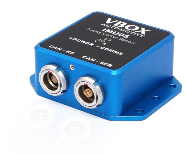
High-precision measurements of pitch, roll, and yaw rate using three industry leading gyroscopes, as well as x, y, z acceleration via three accelerometers.
IMU05 is available in two versions. The regular model features three top-tier, highly accurate gyroscopes with a bias stability of 1.2°/hr, whilst the S model measures roll, pitch, and yaw rate using three outstanding MEMS high-precision gyroscopes that maintain a bias stability of just 0.8°/hr.
Both options can be used as a standalone sensor, with easy connectivity and configuration options through the CAN or serial interface or in conjunction with VBOX data loggers, allowing for precise synchronisation to GNSS time.
Data from the IMU can be seamlessly integrated with GNSS data from a VBOX 3i or VBOX 4 to enhance measurement accuracy when GNSS signal reception is interrupted or weakened.
Key Features

GNSS Integration
When used in conjunction with VBOX as an inertial navigation system (INS), data from the IMU can be seamlessly integrated with GNSS to produce accurate position, velocity and body angles, even during GNSS interruptions.

Fast Initialization
With advanced calibration and low noise, VBOX 4 and IMU05-S achieve full accuracy after a simple accel/brake event – no large spaces or repeated figure-eights needed, so you can start testing immediately.

High Accuracy
Using synchronous 32-bit sampling for each of the internal sensors provides a high degree of accuracy, with angular rate resolution of 2.5 x 10⁻¹⁰ °/s and acceleration resolution of 5 x 10-14 g.

Low Drift/ Low noise
The bias/drift over the course of an hour is as low as 0.8 degrees for an IMU05-S (1.2°/h for IMU05), keeping results stable over time, reducing recalibration and improving confidence in long runs.

Internal Temperature Compensation
The IMU is fully calibrated for temperature effects, scale factor, bias and misalignment errors to ensure consistent performance across hot/cold test conditions.

CAN Bus Interface
When used as a standalone sensor, the IMU05 can be easily connected and configured via the CAN or serial interface into existing test setups.
Which IMU is right for you?
The standard IMU05 gives you high-precision measurements of pitch, roll, and yaw rate, as well as x, y, z acceleration at a very competitive price. IMU-S uses the cutting-edge MEMS gyro technology which improves bias stability, acceleration range and resolution even further.
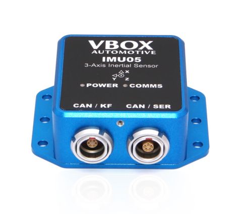
IMU05
1.2°/h bias drift
±450°/s angular rate range in each axis
±4 g acceleration range in each axis
Internal temperature compensation
2.5 x 10⁻¹⁰ °/s angular rate resolution
5 x 10-14 g acceleration resolution
CAN or Serial interface
0.02° RMS Pitch/Roll angle with VBOX 4
0.1° RMS Yaw angle with VBOX 4
IP65/ IP67 with Lemo blanking plugs
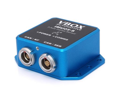
IMU05-S
0.8°/h bias drift
±450°/s angular rate range in each axis
±10 g acceleration range in each axis
Internal temperature compensation
2.5 x 10⁻¹⁰ °/s angular rate resolution
6 x 10-13 g acceleration resolution
CAN or Serial interface
0.013° RMS Pitch/Roll angle with VBOX 4
0.07° RMS Yaw angle with VBOX 4
IP65/ IP67 with Lemo blanking plugs
IMU Integration
Survey-grade high-speed GPS/GNSS is the most accurate way to measure velocity - as long as view to the sky is clear. Challenges occur when buildings or tall trees obstruct the testing ground, causing GNSS signal interruptions and resulting in data dropouts and spikes, which compromise the cleanliness of the velocity signal.
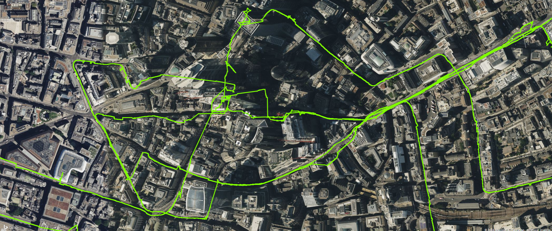

To maintain high GNSS precision even with limited sky visibility, we integrate data from an Inertial Measurement Unit (IMU) with the VBOX data logger.
By blending GNSS with IMU data, which includes three gyros and three accelerometers, we produce smoother and more reliable data. This integration effectively handles GPS dropouts, ensuring consistent accuracy. The IMU integration allows VBOX to achieve high precision even in compromised external conditions, making the data more reliable and easier to interpret.
How does IMU Integration improve the GPS data?
Velocity
Heading
Position
Acceleration
Brake Testing using IMU Integration
Conducting brake tests on tall vehicles with long suspension travel can result in a speed overshoot of the velocity data, due to the measurements being taken at the high roof position of the GPS antenna. As the brakes are initially applied, there is a higher rate of change in velocity at the roof than there is at the vehicle's centre of gravity (COG).
However, the integration of an IMU with a suitably upgraded VBOX 3i or VBOX 4 can be used to counteract this 'lever-arm' effect by placing the IMU at the COG, which measures the vehicle pitch as it brakes. This data, when combined with that from GPS, provides a compensation for the overshoot and allows for consistent brake stop testing.
Counteracting the lever-arm effect will also aid test engineers when conducting high-dynamic manoeuvres other than brake stops. In slip angle measurements, the speed overshoot can occur if the antenna is moving through a greater arc of travel than that of the vehicle's centre of gravity as it corners. Procedures such as lane change manoeuvres can therefore benefit from IMU integration and lever-arm compensation.
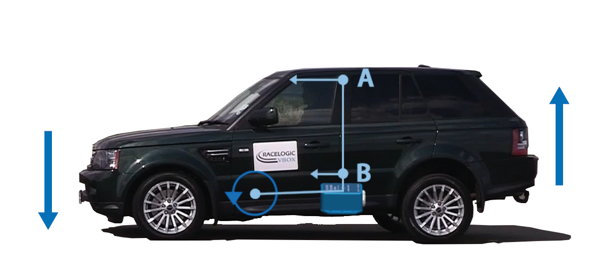
Point A has travelled further than point B.

Blue trace = GPS Speed; Red trace = IMU-corrected data
In this example of a high-dynamic brake stop, the blue trace (GPS Speed) overshoots at the initial point of brake application, and then exhibits a damped oscillation as the deceleration continues. The IMU-corrected data (red trace) accurately records the brake stop from the vehicles centre of gravity.
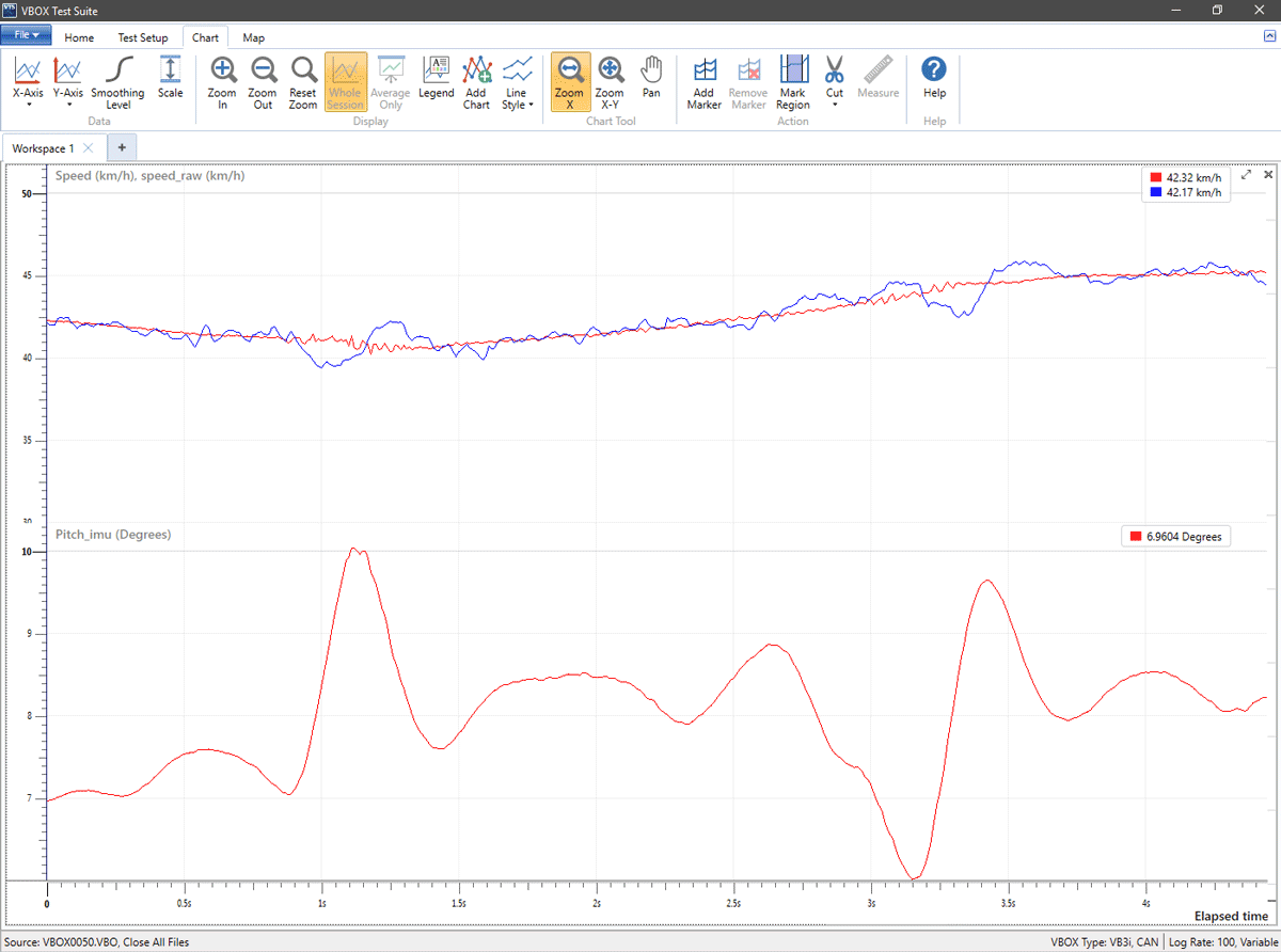
Red (below) = Pitch measured by the IMU; Blue = GPS speed; Red = IMU integrated GPS speed
The traces are of a car going over a speed hump. Note how the GPS speed alters as the vehicle roof moves independently of the COG as it goes over the hump. The integrated speed logs the correct speed of the vehicle.
Mounting Options
1) On the roof
The easiest method of mounting the IMU is by placing it directly on the vehicle roof, co-located with the GPS antenna.
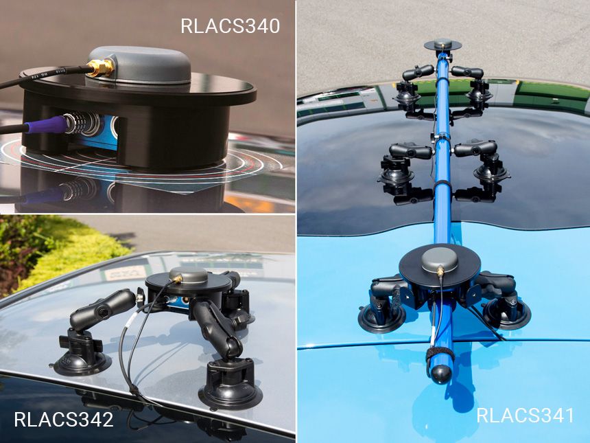
A specially designed IMU roof mount allows for an IMU05 to be securely fastened within the machined enclosure, while its magnetic base ensures that it stays safely in place.
The antenna can then be placed or screwed directly on top of the IMU Roof Mount (RLACS340 for magnetic antennas) allowing for the data sources to be measured at the same point.
By co-locating the antenna and IMU on the vehicle’s roof the distance between the two does not have to be measured, as you do in a standard setup, leaving only the required translation to – typically – the vehicle’s centre of gravity. This method is easier and isn’t prone to human measurement error. Co-locating the antenna with the IMU also greatly improves the performance of the Kalman filter.
When using a vehicle with a non-ferrous roof such as aluminium, carbon fibre or glass (sunroof), the magnetic based IMU Roof Mount will not hold, and a suction mount is required along with the magnetic base.
With its three points of contact, the Vacuum Tripod Mount (RLACS342) ensures a very stable fixture and reduces IMU vibration that might be transmitted by the vehicle's roof.
The adjustable lever arms allow for the levelling of the IMU on a non-flat roof whilst extending the mounting options on the vehicle. For example, you can fix the mount partially or fully on a coupé's glass roof when trying to achieve a greater antenna separation in a dual antenna setup.
If you are testing with a dual antenna VBOX and need maximum antenna separation*, using a Roof Mounting Pole (RLACS171) in combination with the Pole Mount with Ferrous Plate (RLACS341) will enable quick antenna alignment.
An additional pair of pole suction arms is supplied to stabilise the IMU on the roof.
*Maximum antenna separation improves the accuracy of slip angle measurement
2) Within the vehicle using a mounting arm
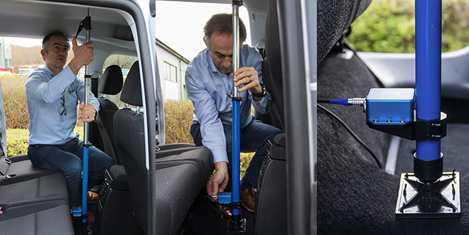
If roof mounting of the IMU is not possible the IMU can be fixed inside the vehicle. A flexible way to fix the IMU rigidly within the vehicle is by using the Racelogic mounting pole (RLACS212-v2). The three-part telescopic handle is fully adjustable to any length between 70 and 150 cm to which another 20 cm can be added by extending a third section using the compression lever.
Both ends are fixed to an 8 x 13 cm plate which sits on a joint to accommodate for uneven surfaces. The IMU can be screwed on the additional IMU pole mount bracket (RLACS294) which firmly sits around the pole. Pressed against the floor and the vehicle's ceiling, the mounting prop ensures that the IMU is fixed tightly.
3) Within the vehicle fixed to the vehicle body
It is also possible to fix the IMU firmly to the body of the vehicle. Make sure it is mounted in the direction of travel - as shown in the image below. It is also important to mount the sensor so that it is level with the ground.
For best results, mount the IMU and GNSS antenna as close to each other as possible. For example: Bolt the IMU to the seat rails and place the GPS antenna on the roof directly above.
You must also measure the relative position of the antenna in relation to the IMU to within +/- 5 cm. These distances can then be entered into the VBOX either via VBOX Test Suite > VBOX Setup or using a VBOX Manager.

Technical Specifications
Please note that inertial measurement sensors are highly sensitive mechanical systems. Their performance and life span can be impacted by severe vibration or heavy knocks, and we can only guarantee the gyroscope and accelerometer specifications for a maximum of 2 years from the date of purchase.
Gyroscopes
- Dynamic range
- ±450°/s
- Bias stability
- ±1.2 °/h
- Angle random walk (ARW)
- 0.08 °/√h
- Scale factor
- 0.05%
Gyroscopes
- Dynamic range
- ±450°/s
- Bias stability
- ±0.8°/h
- Angle random walk (ARW)
- 0.06°/√h
- Scale factor
- 0.05%
Accelerometers
- Dynamic Range
- ±4 g
- Bias stability
- 14 μg
- Velocity random walk (VRW)
- 0.02 (m/s)/√h
- Scale factor
- 0.1%
- Linearity (% of full-scale range)
- 0.1%
Accelerometers
- Dynamic Range
- ±10 g
- Bias stability
- 12 μg
- Velocity random walk (VRW)
- 0.025 (m/s)/√h
- Scale factor
- 0.1%
- Linearity (% of full-scale range)
- 0.1%
Environmental & Physical
- Operating Temperature
- -40 to +85 °C
- Shock survival
- 1000 g (Half-sine, 0.5 msec)
- Power consumption
- < 1 W
- Input Voltage
- 7 – 30 V DC
- Dimensions
- 60 x 76 x 29 mm
- Mass
- 160 g
- Environmental protection
- IP65 rating / IP67 with RLACS080 blanking plugs
View datasheet for full specifications for VBOX IMU05.
View datasheet for full specifications for VBOX IMU05-S.

